
The common faults of the inverter during use are classi […]
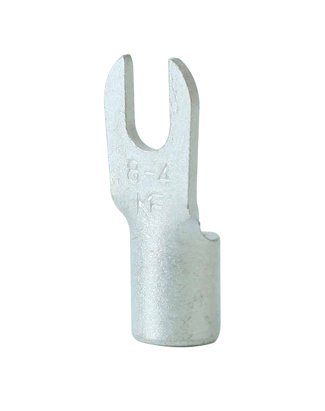
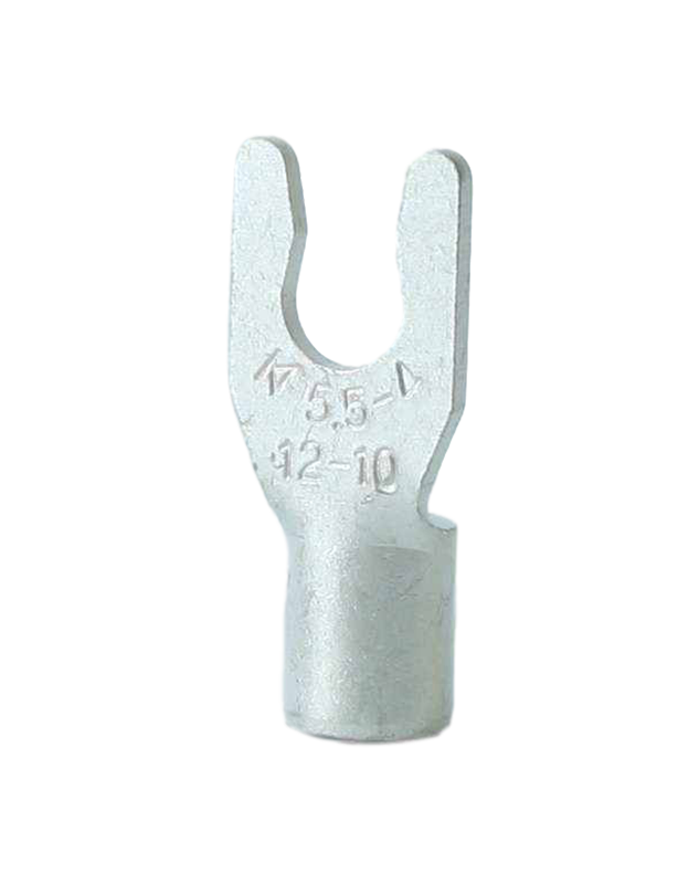
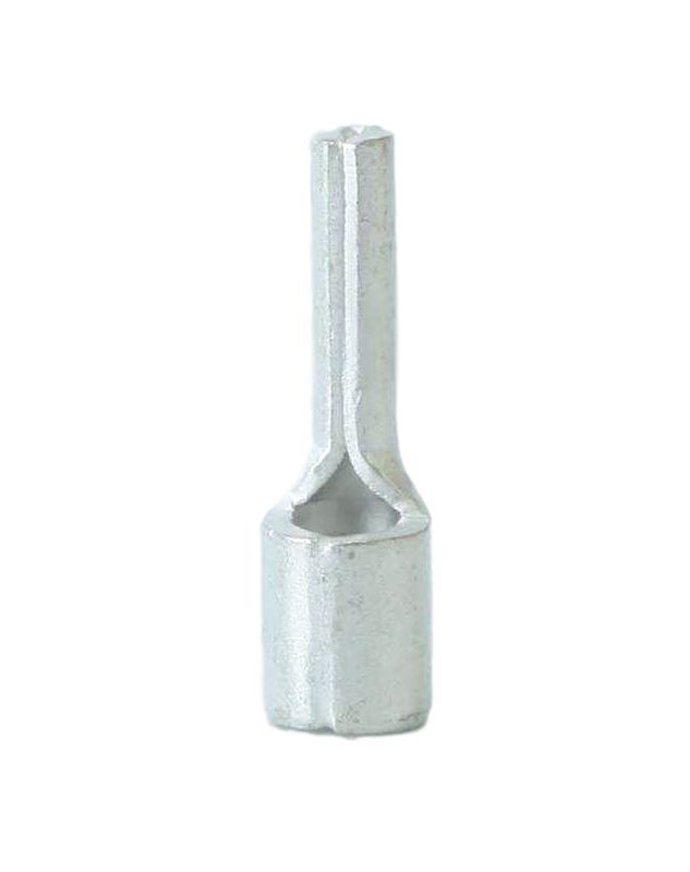
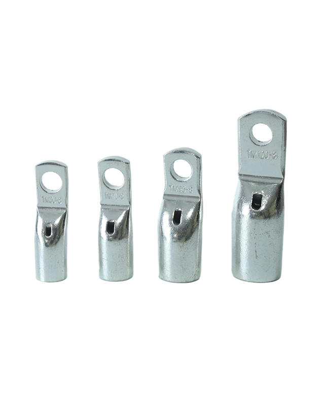
The common faults of the inverter during use are classified into the following categories: 1. Status fault; 2. Hardware fault; 3. System fault; 4. Communication fault; 5. Power failure monitoring. As a common inverter accessory product, the terminal block can also affect the output efficiency of the inverter due to the difference in its connection performance. Now the common situations in which inverter products cannot be used due to the problems of the terminals themselves are listed to present you with the most comprehensive solution to inverter terminal problems.
First of all, we should learn more about the causes of the common faults of the inverter?
1. Status fault: DC over/long voltage, DC over current, AC over current, excessive speed deviation, ground fault, lack of equality.
2. Hardware failure: current board failure, trigger board failure, IGBT failure, pulse generator failure, etc.
3. System failure: Watchdog failure, abnormal system parameter, clock failure, etc.
4. Communication failure: TIMEOUT, OVERRUN, etc.
5. Power failure: alarm when the control power supply is too high or too low.
Next, let us analyze the terminal problem in detail:
1. No display on the operation panel of the switching power supply:
Firstly, the control voltage of the control terminal and the 10V frequency adjustment voltage should be measured. If it is zero, the terminal is in normal use. Otherwise, a higher-quality connection product needs to be replaced; secondly, measure whether the resistance of the main wiring terminal of the inverter is normal;
2, the inverter cannot measure the data when entering the wire:
When viewing the fault record in the inverter menu, no fault is found, but the operation of each button on the operation panel is recorded in the event record. Check that the LED indicators on the A10 main board and A22 power supply board in the inverter are normal. Use a test pencil to test the incoming power supply of the inverter. It is found that one phase is abnormal. The three-phase measurement result with a multimeter is: Vab=390V, Vac= 190V, Vbc=190V. After inspection, the terminal block of the incoming line is in poor contact.
3, the carbonization of the terminals in the inverter module:
When checking the inverter module for no bad symptoms, check the poor insulation between each terminal and the ground. Once it is found that the plastic insulated terminal between the DC bus loop terminals P-P1 and N has signs of carbonization, replace it from a safety point of view If the terminals of the inverter are damaged, the inverter can resume normal operation.
You can tick the products you need and communicate with us in the message board.


Allen.Mo


Jackie.Li


Jasmine.Zhang


Jon.Sun


Roy.Liu