

Learn how to select a copper tubular lug by wire range, stud size, dimensions, body configuration, and barrel/tool match using KF Terminals Type DT data.
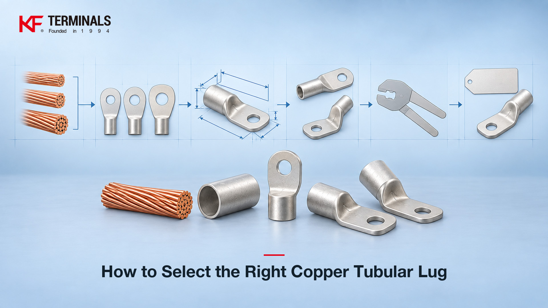
Select a copper tubular lug by matching wire range first, then stud size, then lug dimensions and the crimping tool specified for the barrel size.
That sequence is more reliable than choosing a lug by appearance alone. A complete selection has to connect three dimensional requirements: the conductor size, the stud or mounting-hole requirement, and the physical envelope of the lug. The crimping tool then has to match the selected barrel size.
The KF Terminals copper tubular lugs category groups multiple model families around this selection logic, including Type DT, DTGA, DIN 46235, T, T-90, TT, WB, WB-90, LYF, LYF-90, TM, C45, and AWG.
This guide explains how to read those choices systematically.
Copper tubular lugs can look similar while having different wire ranges, stud holes, overall lengths, barrel dimensions, or installation geometries. That means visual similarity is not enough to establish interchangeability.
The practical selection question is not:
“Which lug looks like the one I already have?”
It is:
“Which lug matches the conductor, the mounting point, the available installation space, and the required crimping arrangement?”
A useful selection sequence is:
This matters because one wire range can correspond to more than one SKU.
For example, the sample Type DT data supplied for a 2.5 mm² / A.W.G. 14 conductor includes three separate entries with 4 mm, 5 mm, and 6 mm stud options. Across those three rows the barrel bore and barrel outside diameter (d and D) and the center distance (E) stay the same, while the stud-hole diameter (d2), the palm width (B), and the overall length (L) change.
That is why a copper tubular lug size chart is more useful than a shape-only catalog view.
For detailed Type DT data, see the Type DT copper tubular lug page.
A practical lug selection can be treated as three connected size chains.
The first question is the conductor size.
The KF Type DT data presents conductor ranges using AWG and mm² references, with larger conductor ranges also expressed in MCM. MCM, also written as kcmil, is a North American conductor-size unit used for larger conductor sizes.
Wire size should be established before comparing stud holes or external lug dimensions. Starting with the stud hole can produce a mechanically mountable part that does not match the conductor.
For additional AWG and metric-size context, see the AWG vs. mm² wire and terminal size guide.
After the conductor range is fixed, the next requirement is the mounting stud.
The supplied Type DT sample rows show stud-size combinations such as:
The stud requirement cannot be treated as a secondary cosmetic difference. For the same conductor range, different stud holes can correspond to different SKUs and different surrounding dimensions.
A lug selected for the wrong stud size may not fit the mounting point or may provide the wrong mounting geometry for the installation.
The third chain is the physical size of the lug itself.
The Type DT table includes six dimensional fields:
These values allow the engineer or buyer to compare the hole, palm, barrel, total length, and installation envelope rather than assuming that all lugs for the same conductor size are physically identical.
The result is a three-part selection rule:
Wire range → stud size → dimensions
Only after those three have been checked should the final tool requirement be confirmed.
The supplied Type DT data provides the following wire-range and maximum-current relationship.
| Wire Range | Max Current (A) |
|---|---|
| 16 AWG | 18 |
| 14 AWG | 30 |
| 12 AWG | 35 |
| 10 AWG | 50 |
| 8 AWG | 70 |
| 6 AWG | 95 |
| 4 AWG | 125 |
| 2 AWG | 170 |
| 1/0 AWG | 230 |
| 2/0 AWG | 265 |
| 3/0 AWG | 310 |
| 4/0 AWG | 360 |
| 250/300 MCM | 445 |
| 300/350 MCM | 505 |
| 400 MCM | 545 |
| 500 MCM | 620 |
| 600/750 MCM | 785 |
| 800/1000 MCM | 935 |
| 1000/1250 MCM | 1065 |
The table shows the basic relationship that larger wire ranges correspond to higher current values in the supplied product data.
However, current is only one selection input. It does not replace the dimensional check.
A buyer who identifies the conductor range still needs to determine:
The supplied Type DT information also includes a separate metric size sequence, listed independently of the AWG column:
1.5 / 2.5 / 4 / 6 / 10 / 16 / 25 / 35 / 50 / 70 / 95 / 120 / 150 / 185 / 240 / 300 / 400 mm²
When a North American wire-size reference is preferred, the AWG copper tubular lug family provides a separate family page within the same copper tubular lug category.
The key point is that conductor range narrows the selection. It does not complete it.
The Type DT data structure includes the following fields:
Wire Range | SKU# | Description | MFG# | Stud Size | Dimensions (d2, B, L, D, d, E) | Tool
The site data does not separately define each dimensional symbol. For selection purposes, the following labels are therefore used here as neutral dimensional references based on the supplied engineering interpretation rather than as claimed manufacturer definitions:
These labels are useful because they turn a product drawing into a dimensional checklist.
The following rows reproduce only the verified sample data supplied in the brief.
| Wire Range | SKU# | MFG# | Stud Size | d2 | B | L | D | d | E |
|---|---|---|---|---|---|---|---|---|---|
| A.W.G. 16 / 1.5 mm² | KFLDT10 | DT1.5-4 | #10 / 4 mm | 0.205″ / 5.20 | 0.315″ / 8.00 | 0.709″ / 18.00 | 0.157″ / 4.00 | 0.087″ / 2.20 | 0.394″ / 10.00 |
| A.W.G. 14 / 2.5 mm² | KFLDT20 | DT2.5-4 | #8 / 4 mm | 0.165″ / 4.20 | 0.315″ / 8.00 | 0.748″ / 19.00 | 0.177″ / 4.50 | 0.114″ / 2.90 | 0.512″ / 13.00 |
| A.W.G. 14 / 2.5 mm² | KFLDT21 | DT2.5-5 | #10 / 5 mm | 0.205″ / 5.20 | 0.32″ / 8.00 | 0.787″ / 20.00 | 0.177″ / 4.50 | 0.114″ / 2.90 | 0.512″ / 13.00 |
| A.W.G. 14 / 2.5 mm² | KFLDT22 | DT2.5-6 | 1/4″ / 6 mm | 0.252″ / 6.40 | 0.39″ / 10.00 | 0.787″ / 20.00 | 0.177″ / 4.50 | 0.114″ / 2.90 | 0.512″ / 13.00 |
These four rows illustrate an important selection principle.
KFLDT20, KFLDT21, and KFLDT22 all reference A.W.G. 14 / 2.5 mm², but they are not the same part. Their stud sizes differ, and the corresponding d2, B, and L values are not identical across all three rows.
Therefore, specifying only “2.5 mm² copper lug” is incomplete.
A more complete purchasing specification should identify at least:
wire range + stud requirement + dimensional match + model/SKU
This reduces ambiguity when more than one lug serves the same conductor range.
KF Terminals groups copper tubular lugs into several model families rather than presenting every configuration as one undifferentiated list.
The supplied family set includes:
The family code should be treated as one part of the selection process, not as a substitute for dimensional verification.
The supplied selection logic identifies several ways in which model families may be grouped: straight versus 90° arrangements, different tubular-body configurations, open versus closed configurations, a family identified by the DIN 46235 name, and a family organized around the AWG sizing system.
The exact family page should therefore be consulted after the application requirements have been established.
For buyers comparing the broader range of lug configurations, the existing article Copper Tubular Lugs Are Available in Various Types can be used as a type-oriented reference, while this guide focuses specifically on dimensional selection.
For applications involving a different terminal category rather than a tubular lug, the non-insulated terminals category provides a separate product-family reference.
A straight lug and a 90° lug can solve different mechanical routing problems even when conductor size is already known.
A 90° configuration is particularly relevant where the available space behind a panel or inside a cabinet restricts straight cable routing. In these conditions, the body direction becomes part of the dimensional selection.
KF Terminals lists 90° families including T-90, WB-90, and LYF-90 within the copper tubular lug range.
Two linked examples are:
The important engineering question is not simply whether a 90° version exists. It is whether the selected geometry fits the actual installation envelope.
Before choosing between straight and angled configurations, check:
This is another reason that the L, B, d2, and other dimensional fields need to be reviewed together rather than independently.
An apparently small difference in overall geometry can determine whether the cable can be routed without interference.
The crimping tool must match the selected barrel size.
This step should come after the conductor, stud, model family, and lug dimensions have been selected. A correct dimensional match between cable and lug does not by itself establish the crimping-tool match.
The Type DT table structure includes a tool field specifically alongside the wire range, SKU, stud size, and dimensions. The selection procedure should therefore treat the tool requirement as part of the complete lug specification.
Use the crimping tool specified for the barrel size.
The reason is practical as well as dimensional. The quality of a crimped connection depends on the mechanical and electrical interface formed between the conductor and the terminal during crimping, not on the visible contact area alone.
Because the barrel and conductor have to be compressed as a system, uncontrolled tool selection can make the final crimp condition uncontrolled as well.
A practical workflow is therefore:
conductor size → lug barrel → specified crimping tool
Do not reverse this process by selecting a lug merely because it fits an existing tool.
Where tool selection is being reviewed together with terminal selection, see the tools and accessory category.
The following workflow can be used when preparing a technical selection, inquiry, or purchasing specification.
Start with the conductor and establish its size in the system used for the project: AWG, mm², or MCM where applicable.
Do not begin with the stud hole.
The conductor requirement determines the first set of candidate lugs.
Once the wire range is fixed, identify the required mounting hole.
The Type DT sample shows why this is necessary. The same A.W.G. 14 / 2.5 mm² wire reference appears with 4 mm, 5 mm, and 6 mm stud options.
The stud requirement therefore narrows the candidate set further.
Review the dimensional fields together:
Do not confirm a part solely because d2 matches the stud or because d matches the conductor.
The complete lug still has to fit the connection point and surrounding space.
With the dimensional envelope established, review the cable path and the available space around the connection.
If a straight body creates a routing or clearance problem behind a panel or inside a cabinet, evaluate a 90° family.
The bend configuration can change how the cable occupies the installation space, so confirm it before the final part is approved.
After selecting the barrel, use the crimping tool specified for that barrel size.
This keeps conductor, barrel, and crimping arrangement within the same selection chain.
Finally, record the model family and exact SKU rather than relying on a generic description such as “copper lug.”
A useful RFQ or procurement description can therefore be structured around:
model family + conductor size + stud size + dimensional requirement + SKU, where already identified
KF's verified Type DT product information lists the base material as Copper, the finish/coating as Tinned, the brazed construction field as Seam, the insulation field as N/A, and the wire/cable type as Regular Wire.
These product attributes can be reviewed together with the dimensional data when defining the required part.
Select the lug by matching the conductor size first, the stud size second, and the lug dimensions and barrel/tool requirement third. The model family and SKU can then be confirmed after those dimensional requirements are known.
This approach avoids treating visually similar lugs as interchangeable.
Yes, the same wire size can correspond to multiple lug SKUs with different stud sizes or external dimensions. In the supplied Type DT sample, A.W.G. 14 / 2.5 mm² appears in three entries with 4 mm, 5 mm, and 6 mm stud references.
Wire size alone is therefore not a complete purchasing specification.
They are dimensional references used to compare the mounting hole, body or palm envelope, total length, barrel, and center-distance geometry of the lug. In this guide, their individual descriptions are neutral engineering labels used for reading the supplied table and are not presented as manufacturer-defined terminology.
They should be checked together when assessing installation fit.
Consider a 90° lug when panel-back or cabinet space makes straight cable routing difficult. The angled body can address cable-direction constraints, but conductor size, stud size, external dimensions, and tool matching still need to be verified separately.
KF Terminals lists multiple 90° model families within its copper tubular lug range.
Use the crimping tool specified for the selected barrel size. Tool selection should follow conductor and lug selection because the crimping arrangement has to correspond to the barrel being installed.
Do not use lug appearance alone as the basis for selecting the crimping tool.
A reliable copper tubular lug selection starts with measurable requirements: conductor range, stud size, lug dimensions, installation geometry, and barrel/tool compatibility.
Use the KF Terminals copper tubular lugs category to review the available model families.
If you already have the cable size, stud requirement, or target dimensions and need to identify a matching configuration, contact KF Terminals with the required specification.
You can tick the products you need and communicate with us in the message board.


Allen.Mo


Jackie.Li


Jasmine.Zhang


Jon.Sun


Roy.Liu